


Wireless TAC-2
I've had this one TAC-2 controller lying around with a broken cord and one day I just got an idea that maybe I'll convert it to wireless version instead of fixing the cord so I could use it for controlling a robot or whatever comes in my mind. I ordered a set of modules for a 433 MHz RF link from SparkFun Electronics (transmitter and receiver) that are easy to use.
I designed own boards for both modules and both of them have an Atmel ATtiny2313 microcontroller that handles all the serial communication between the links. On the left is the transmitter and on the right is the receiver. I decided to design the first receiver so that it has the same connector and pinout as the original connector so it could be plugged to a Commodore 64 for example (there is a +5V pin on the connector so it can be powered from there). I'll upload the Eagle files later.
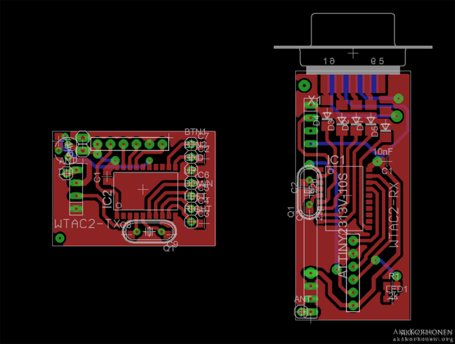
wtac2_eagle_pics_1.png
And this they looked after I made the boards and soldered all the parts on their places.

tx_rx_ak04343_640px.jpg
There was some weird problems with the link. I used some ready program codes for the link to test things out but for some reason it just didn"t want to work. Luckily it was possible to use the good oscilloscopes at school (haven"t managed to get one for myself yet) to be able to do some better debugging of the devices.
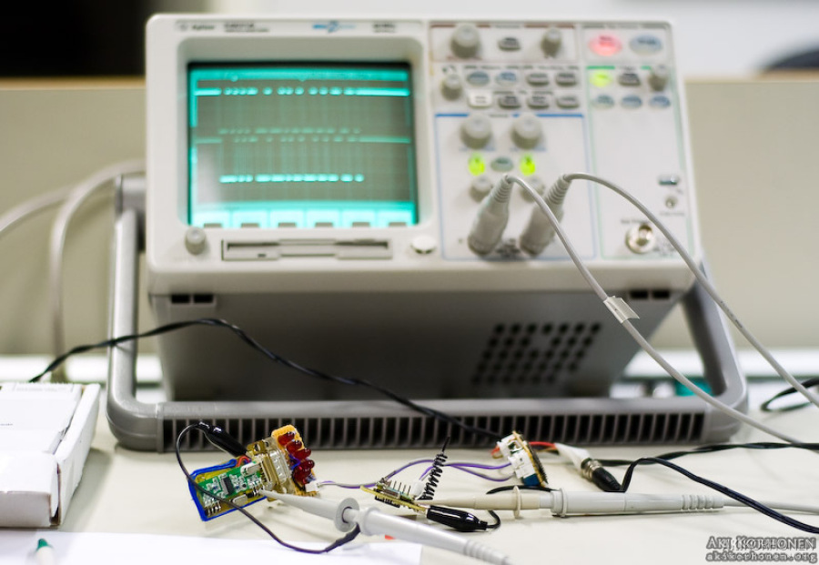
20090126-_ak04976.jpg
On the first debugging time I didn"t manage to find the problem but after thinkering about it for a week I once again went and tried to find the problem and fortunately I solved it. I think that the problem wasn"t in anything I did because after soldering the short red wire on the receiver module all the problems disappeared and the links worked perfectly. On the top you can see the start of the data reception has that weird big trail on the beginning (I compared it to the data on the transmitter and there wasn"t anything like that) and after adding the wire the view was what is in the bottom part, just like it should be: identical with the transmitted data.
I actually found the right place for fixing by poking the circuit with my finger after being frustrated because I didn"t have any clue what is wrong. I noticed that there was a change on the oscilloscope when I poked the right area on the board and started to pinpoint the exact place. The point was connected to the +5V line and just came to my mind that what if I solder a shortcut to the nearest +5V pin and hey presto, it worked!
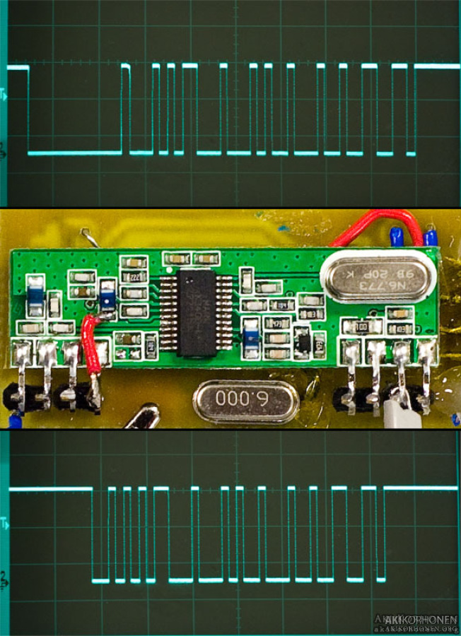
receiver_ak05383.jpg
After finally getting the hardware to do what it supposed to do, I coded the final softwares for the transmitter and receiver and started modifying the joystick to become a wireless one.

m_ak05386.jpg

m_ak05388.jpg
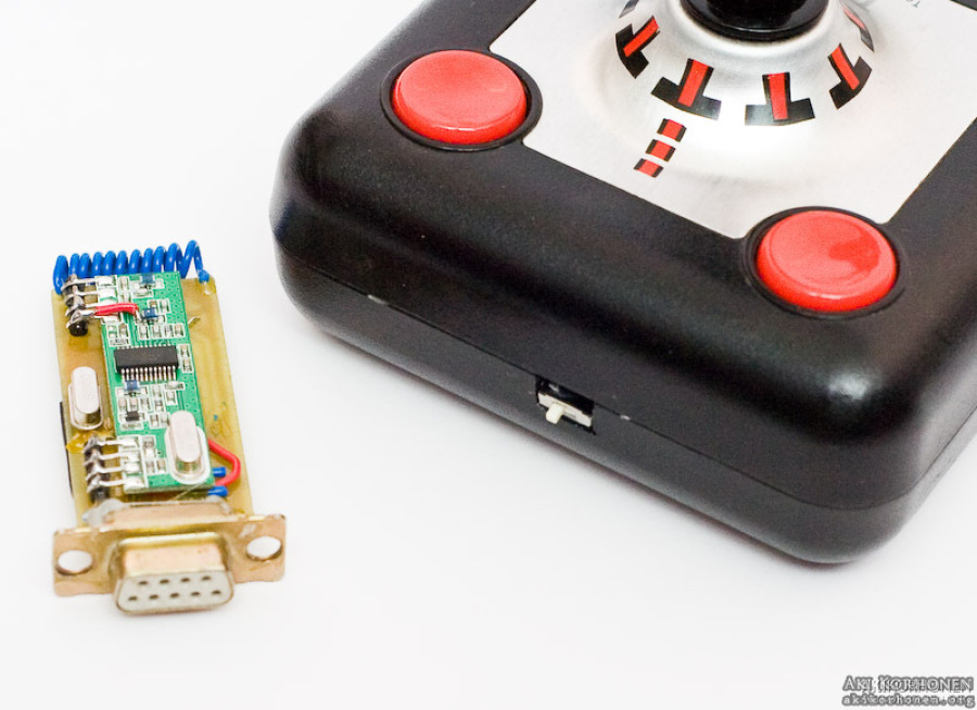
I cut off the remaining piece of wire and soldered all the wires to their own places on the transmitter. I made a little modification and separated both of the buttons so they can be used separately if wanted (the button status is transmitted separately but the first receiver counts the data as one button). The transmitter is powered by one 3V CR2 lithium battery and there is an on/off switch on the hole where the cord was.

m_ak05389.jpg
Receiver and the modified joystick ready (I'll just need to make a case for the receiver or just use some large hot shrink tubing on it). The right photo shows the power switch too.
m_ak05391.jpg
m_ak05392.jpg
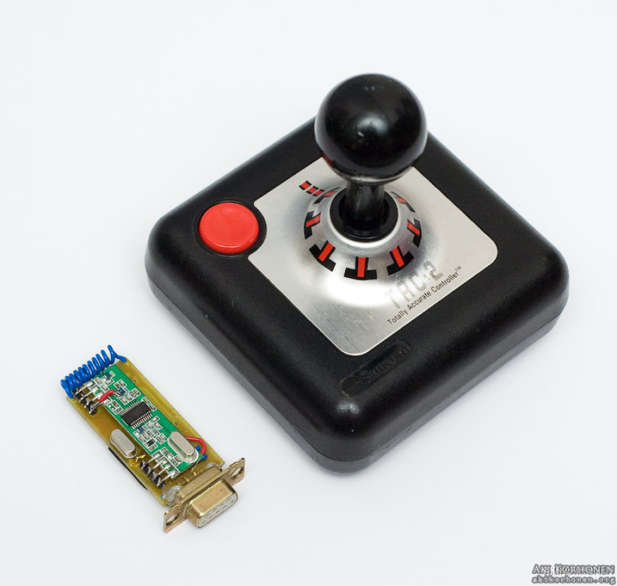
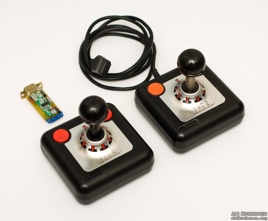
And a little comparison between a wired and wireless TAC-2 joysticks. As some might have noted the one I modified is the "Made in China" version (red buttons and black shaft) which isn"t as good as the "Made in USA" version (orange buttons and metallic shaft). I'll have to test out the compatibility with a Commodore 64 some day, maybe just for fun. I tested the wireless joystick with a Commodore 64 and it seems to work otherwise ok, but not very far at the moment, I'm guessing that the receiver is taking some interference. Good to continue from here anyway.
m_ak05577.jpg
And below are the source codes for the controllers. They should compile without problems with the latest version of WinAVR. The transmitter polls all the buttons and directions all the time and there is a sleep timeout running all the time which is zeroed whenever a change in input state is detected. After roughly 10 seconds the transmitter turns off the power from the transmitter module to save energy and continues polling the inputs. If an input state change is detected the transmitter module is powered on again and the sleep timeout starts running. One datapacket is 4 bytes long (sync + receiver address + data + checksum) and the inputs take 6 bits from the data byte (2 buttons and 4 directions). The receiver checks that the received data is correct and by that it then pulls the right pins to ground.
» Wireless TAC-2 / Transmitter / 2009-02-03
» Wireless TAC-2 / Receiver / 2009-02-03