


Joytech XBox display hacking
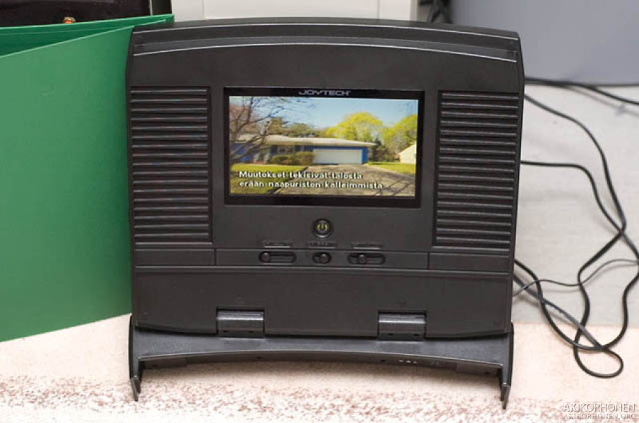
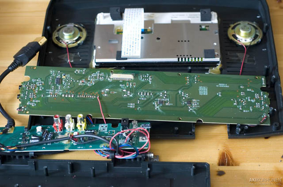
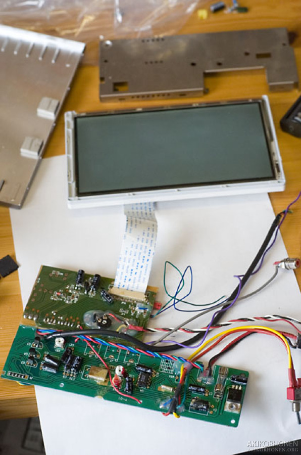
Some time ago I bought three Joytech Ultimate Travel Pack Xbox sets for 15€/set. One set includes 7" display unit, 150W car inverter (12VDC->230VAC), 12V in-house power supply and a big case to hold both xbox and display. I'd say that the value for money goes through the roof at that price. The price was that low because the store wanted to get rid of them I guess, good for me. I disassembled one and started to examine how I could connect the panel to the computer. The panel used in the display unit is Sharp LQ070T3AG02 which has two RGB-inputs.
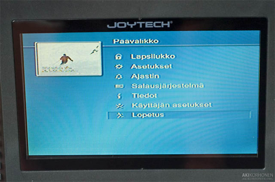
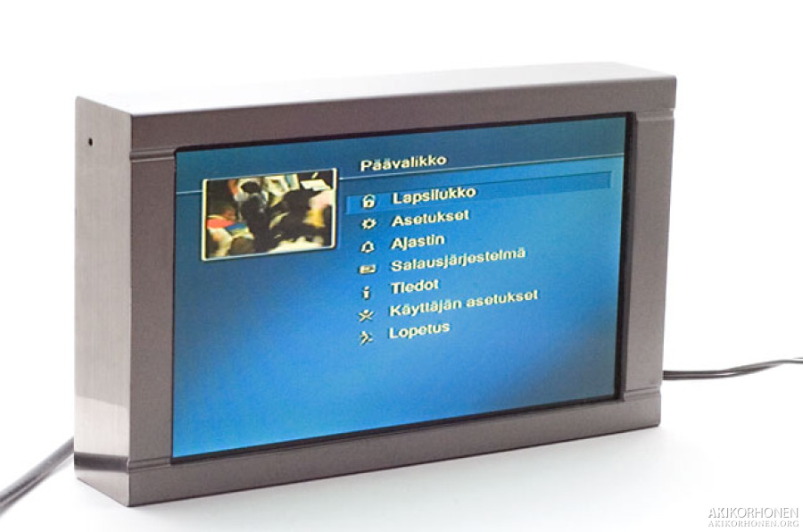
In the first photo the display is connected to a digital tv-receiver with a composite cable.
k_dsc3385.jpg
k_dsc3404.jpg
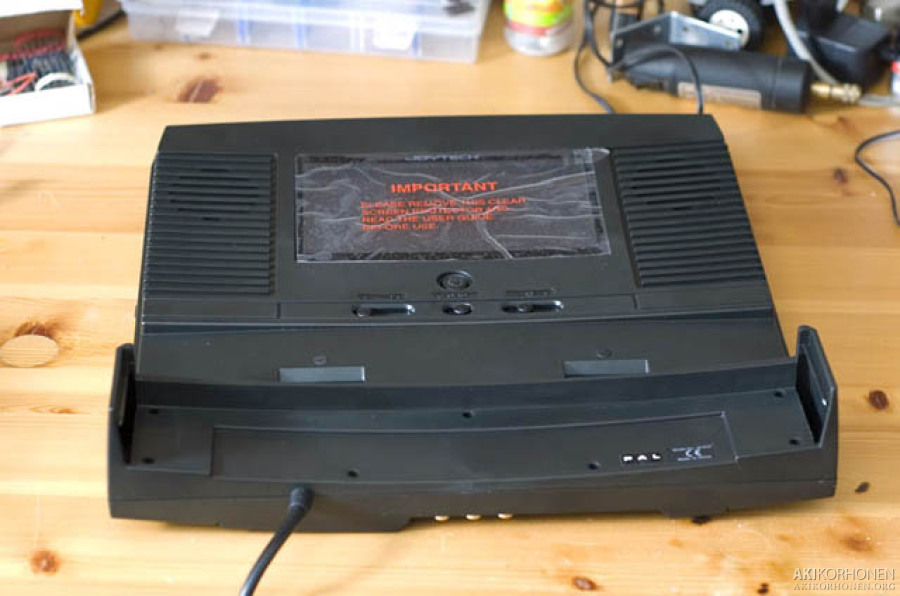
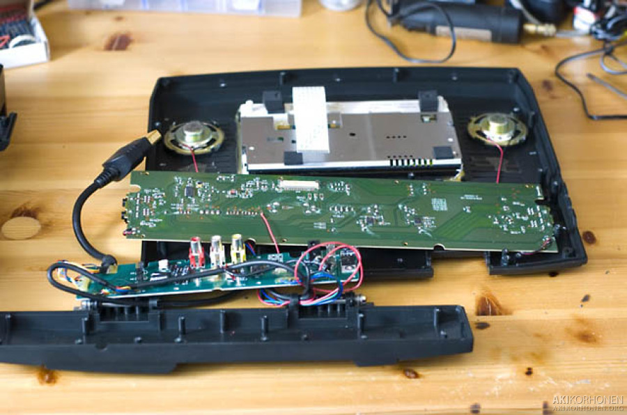
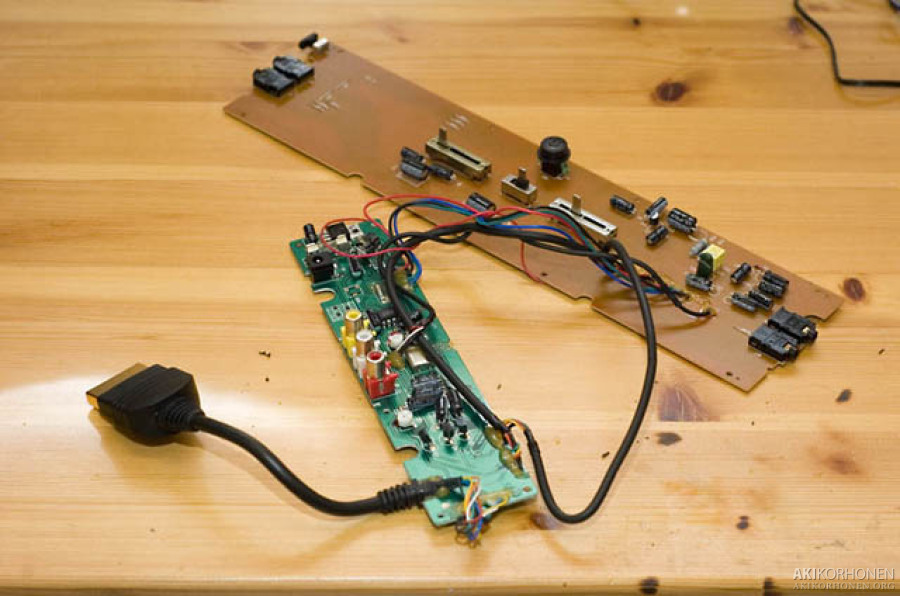
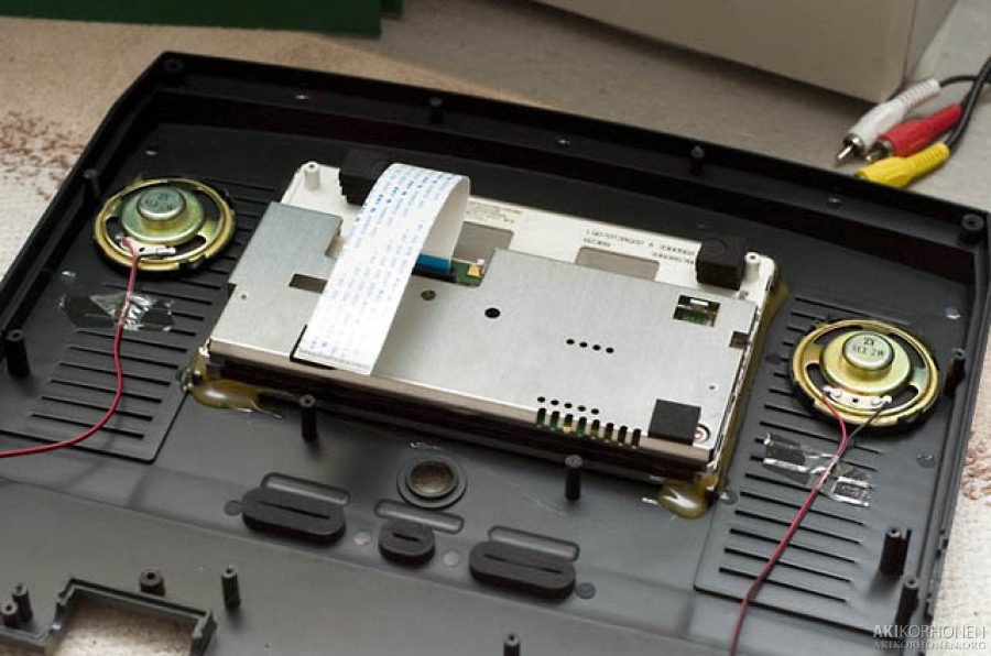
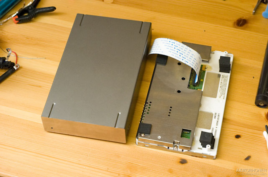
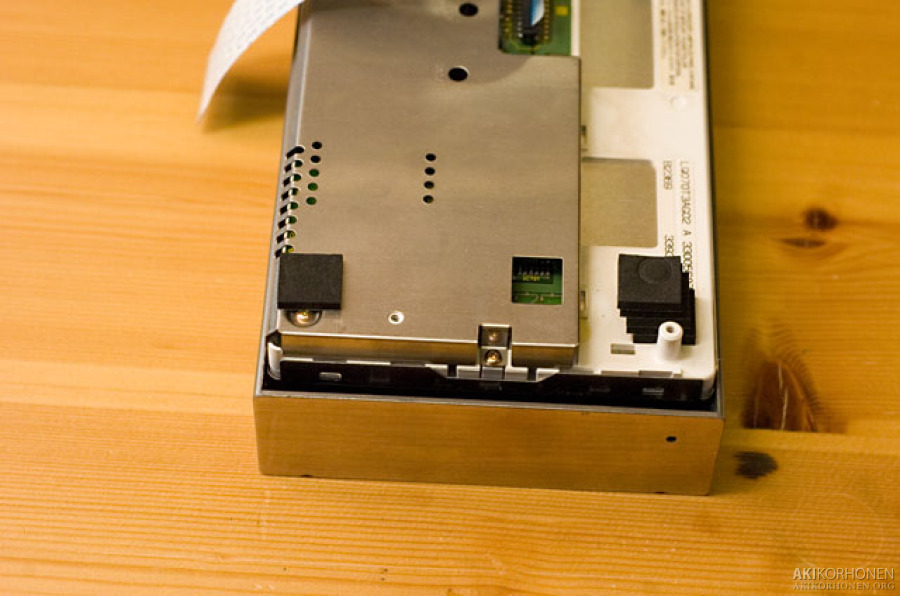
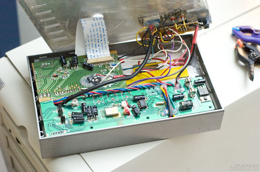
Disassembling the screen.
k_dsc3406.jpg
k_dsc3407.jpg
k_dsc3408.jpg
k_dsc3412.jpg
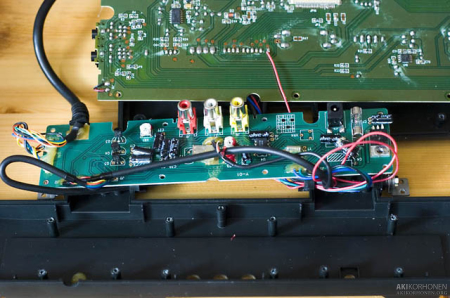
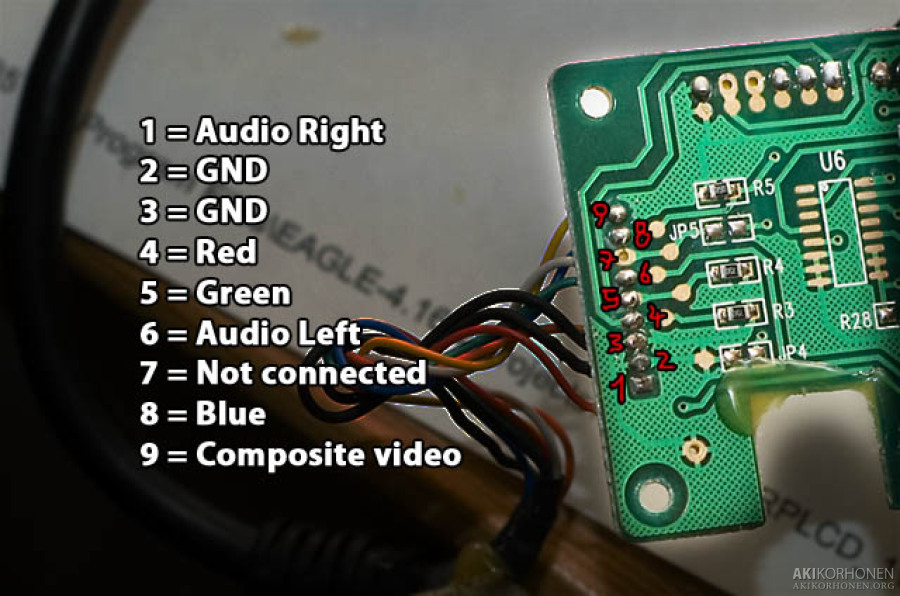
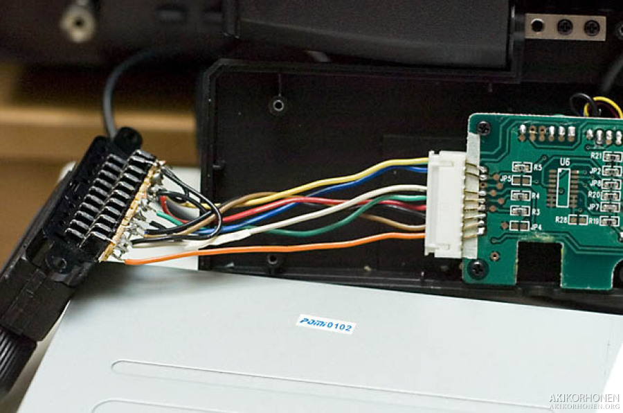
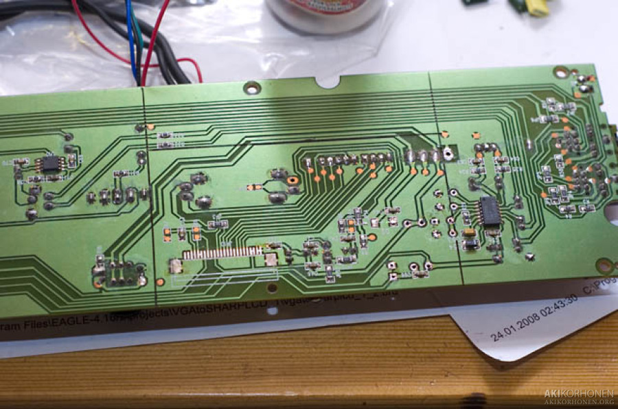
The second picture shows the pcb pinout for the xbox-connector.
PCB	XBOX	SCART				Description
---	----	-----				-----------
1	1	2				Audio Right
2	2	4, 5, 9, 13, 14, 17, 18, 21	GND
3	8	4, 5, 9, 13, 14, 17, 18, 21	GND
4	22	15				Red
5	11	11				Green
6	14	6				Audio Left
7	N/C	N/C				Not connected
8	9	7				Blue
9	24	20				Composite video
k_dsc3413.jpg
k_dsc3431.jpg
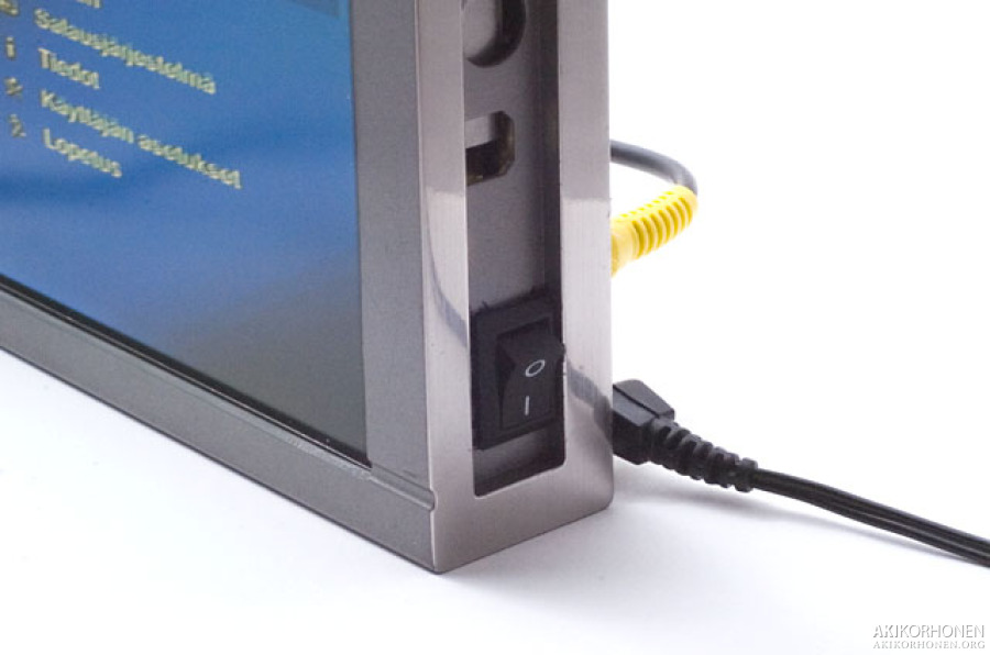
Testing a SCART-connection to the digital tv-receiver.
k_dsc3436.jpg
k_dsc3440.jpg
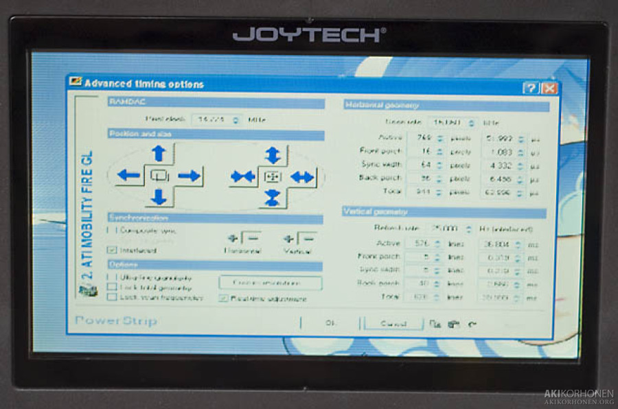
Testing a VGA-connection to the PC.
PCB	VGA
---	---
2	5,6,7,8,10	GND
3	5,6,7,8,10	GND
4	1		Red
5	2		Green
8	3		Blue
9	13		HSYNC or VSYNC
k_dsc3441.jpg
k_dsc3442.jpg
After examining the bigger PCB, I got it narrowed down to the size marked with red lines. That cut modification preserves all video capabilities but takes away the sounds. No problem because the size gets so much better.

k_dsc3507.jpg
k_dsc3619.jpg
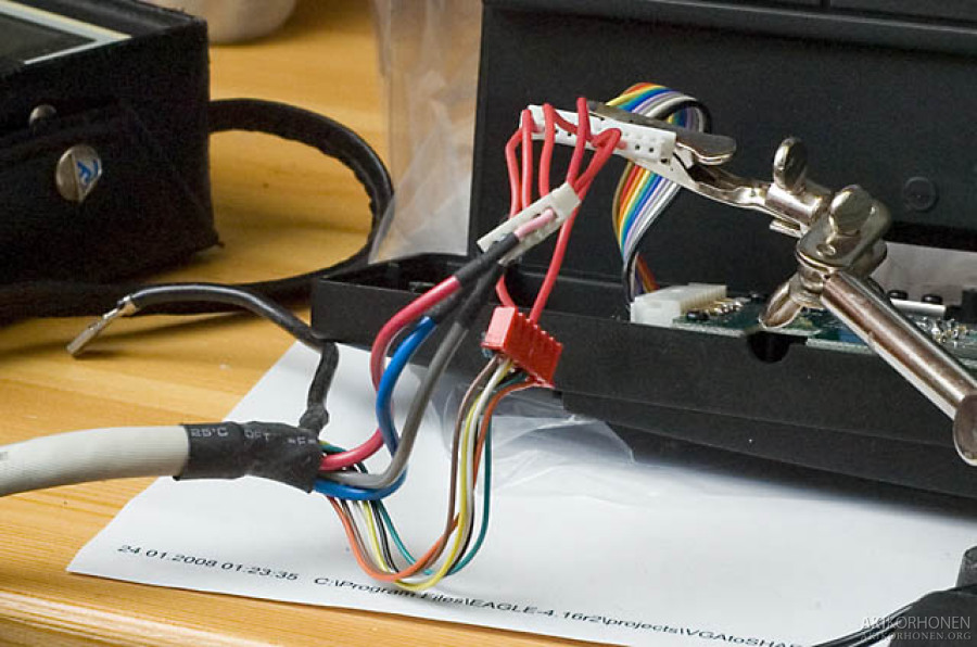
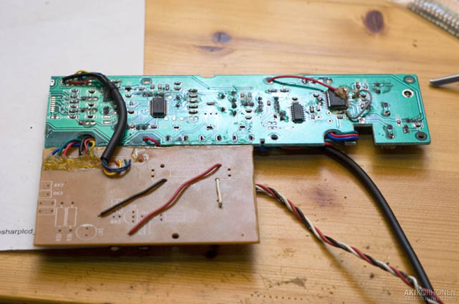
After some cutting and wire soldering, I got the boards to a nice size that will fit behind the panel.
k_dsc3626.jpg
k_dsc3628.jpg
The pinout for the Sharp panel:
 1 HSY -- HORIZONTAL SYNC (VGA13)
 2 VSY -- VERTICAL SYNC (VGA14)
 3 CLK -- DDC CLOCK (VGA15)
 4 NTP -- CHANGE mode Pal/NTSC
 5 HRV -- HORIZONTAL SCAN DIRECTION
 6 VRV -- VERT SCAN DIRECTION
 7 VSW -- SELECTION FROM TWO INPUTS
 8 CLKC -- CHANGE the IO direction of CLK, HSY, VSY
 9 VCDC -- DC BIAS voltage adjust
10 VIN -- POSITIVE VOLTAGE
11 VBS -- COMPOSTE Signal Seperator
12 BRT -- BRIGHT ADJUST
13 VR1 -- RED (VGA1)
14 VG1 -- GREEN (VGA2)
15 VB1 -- BLUE (VGA3)
16 GND1 -- Ground (VGA5-8/10)
17 VR2 --RED 2
18 VG2 -- GREEN 2
19 VB2 -- BLUE 2
20 GND1 -- Ground
21 VBL -- Backlight 12V
22 VBL -- Backlight 12V
23 GND2 -- Backlight ground
24 GND2 -- Backlight ground
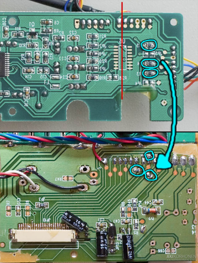
The first photo shows where to cut the smaller PCB and some SMD resistors (75 ohm) to be moved to the other board.
k_dsc3628_2.jpg
k_dsc3696.jpg
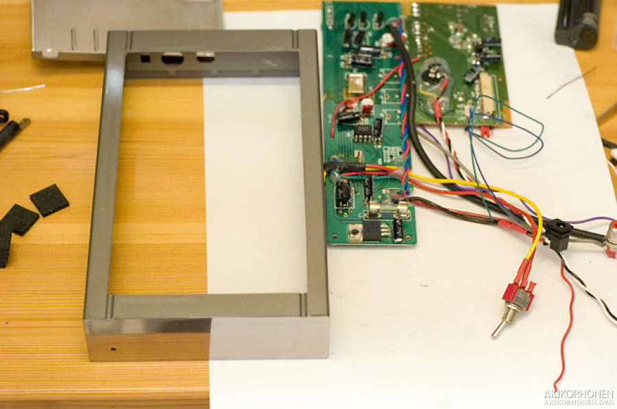
The case for the panel was a kick of good luck. I got an empty case of a Lacie Porche external HDD where the panel fits snugly, only a little bit of sanding was needed on the insides.
k_dsc3692.jpg
k_dsc3694.jpg
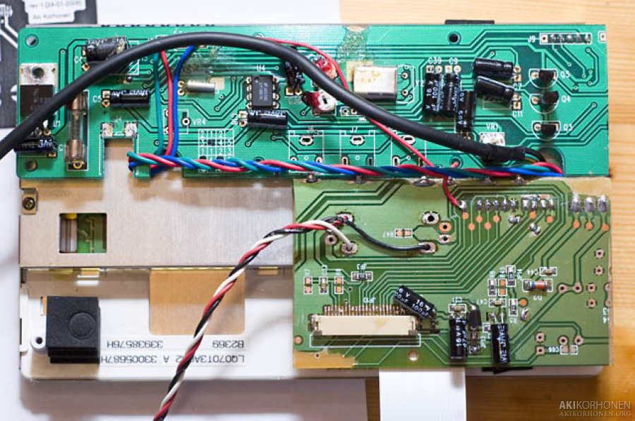
I measured the viewable area of the panel and cut a hole on the case. As you can see from the second photo, there isn"t much free space inside the case.
k_dsc3704.jpg
k_dsc3720.jpg
Display finished. I think it came out very nicely. Only thing missing is a nice stand for it.
k_dsc3741.jpg
k_dsc3744.jpg
k_dsc3749.jpg
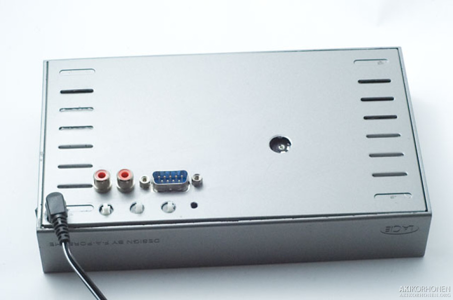
Pinout for the 9-pin D-Sub I used on the back of the display:
D-SUB	Description
-----	-----------
1	R
2	G
3	B
4	GND
5	CSYNC
6	GND
7	HSYNC
8	VSYNC
9	GND