


Rotating led display
I've always liked all kinds of led displays and a rotating one is maybe one of the most interesting ones. I've been planning on building one for many years (actually I made one a couple of years ago, but it is was quite crappy). I finally got some good ideas on how I'll make the first proper display and started to plan the schematics and the pcb with Eagle. You can see the finished ones below.
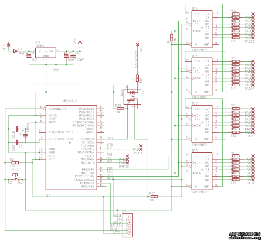
led_display_schematics_1.png
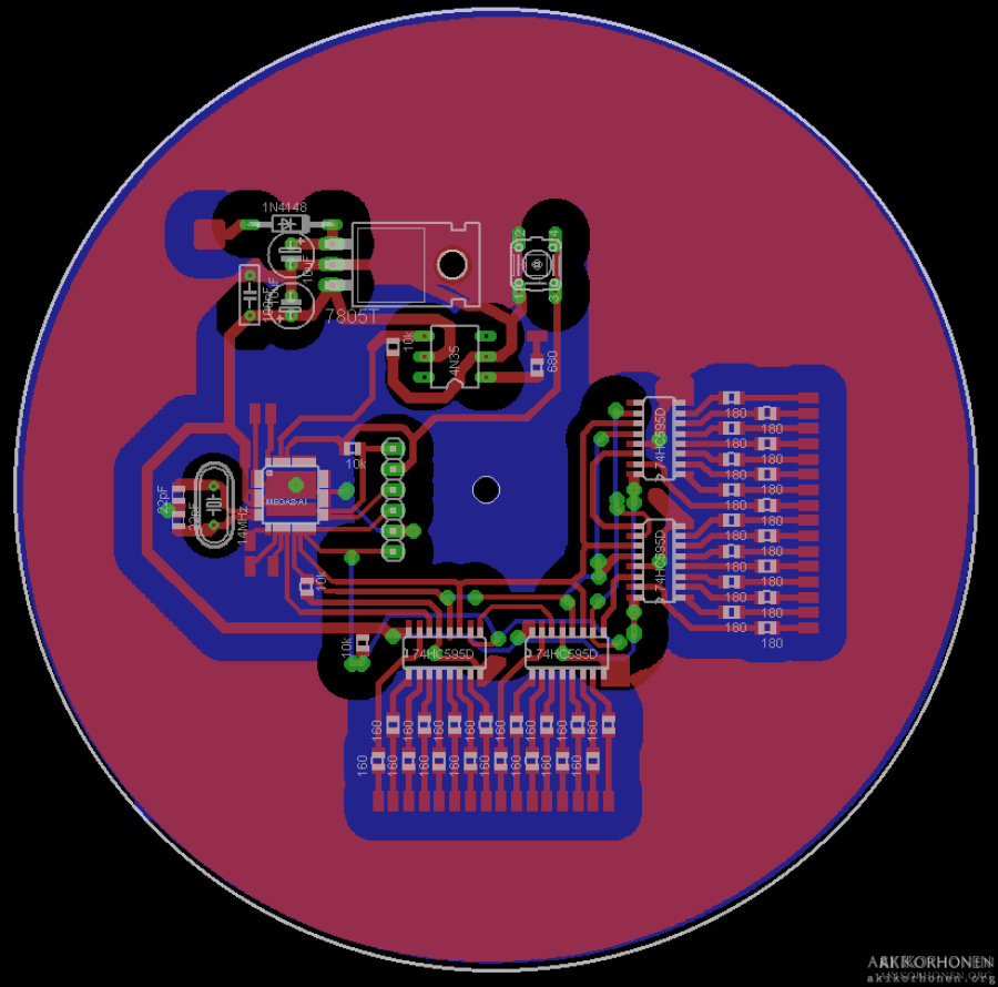
led_display_pcb_1.png
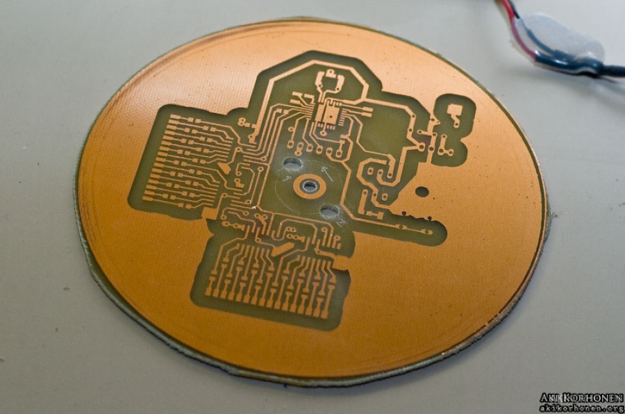
You can see the etched and cut board on the left. It is a double sided pcb with the other side fully coppered to be used as a ground plane. On the right is the motor I used for the display, it is a normal 8 cm fan and I cut the sides away and removed the fan part from the motor. I used this same motor on the first led display I talked about in the beginning.
m_ak07058.jpg

m_ak07056.jpg
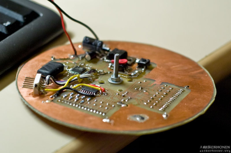
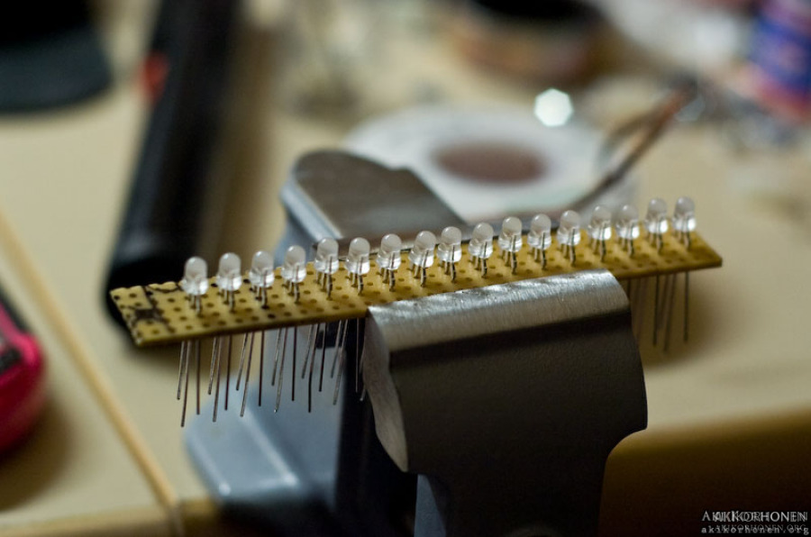
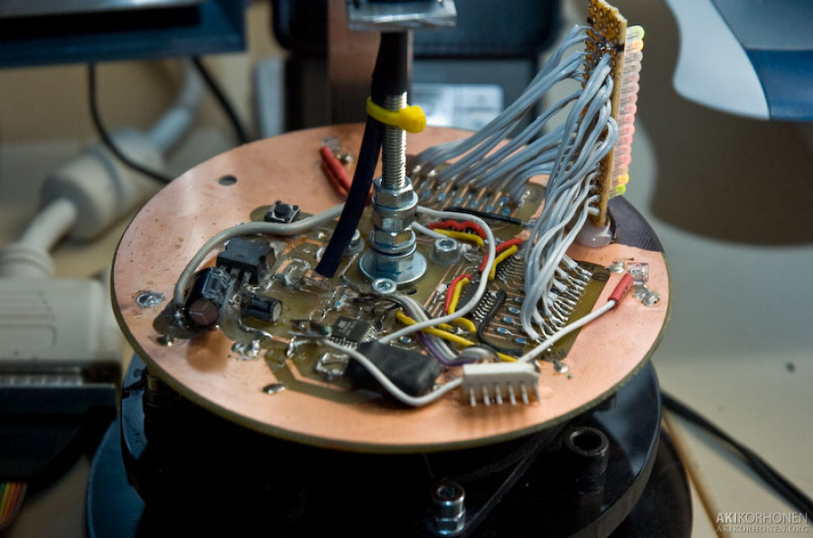
On the left photo the pcb is being populated and most of the 74HC595D shift registers and led current limiting resistors are missing. On the right I'm making the led part. I made this part again later and moved all the leds closer together. I used 16 double color (red+green) leds.
m_ak07422.jpg
m_ak07423.jpg
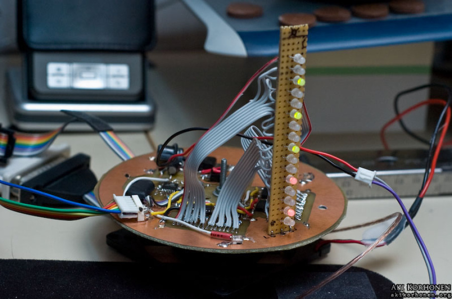
The board fully populated and the first tests on the display running. Just some random tests to see that all the shift registers are working properly and all the data lines are connected right.
m_ak07437.jpg
m_ak07439.jpg
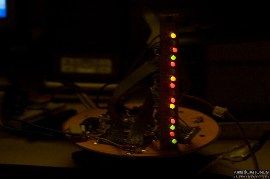
After a couple days of building and fixing I got the machine ready. I did the led part again to get all the leds closer together because I wanted a more even picture and the long version was too wobbly. The rotating board gets its ground through the motor (I soldered a piece of wire to the bearing under the motor) and +12V is coming from the upper bracket seen on the photos. There is a big bearing on the bracket and it is held in place with those four M3 bolts.

m_ak07534.jpg

m_ak07545.jpg
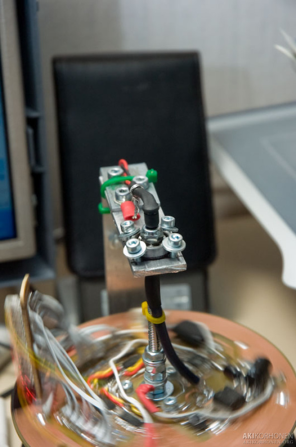
Closeup of the bracket. The black thing pointing down above the bearing is an IR led covered with heat shrink tubing. There is a piece of fiber optic running through the center rod (~10 cm piece of M5 threaded rod) and it goes over an IR-diode on the board. It is used for serial data so I can send some information on to the rotating board. I'll replace this with a wireless link someday.
m_ak07536.jpg
m_ak07540.jpg
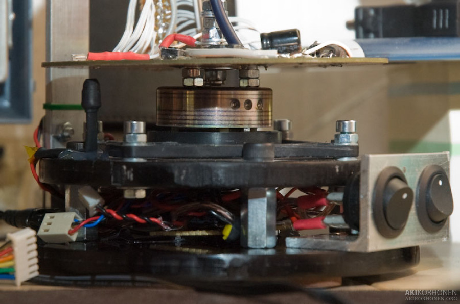
Side shot from the device. The rotating board is connected to the motor with three short M3 bolts. Below the motor there is a small pcb in the middle of those wires with a MAX233 RS232 level converter. The switch on the right is the main power switch and the one on the left is for the motor. The main switch lets power go on to the rotating board so I can program it and after removing the programming cable, I can then switch on the motor. There is also another IR led under the rotating board that is used to trigger the IR diode on the board that is connected to the INT0 interrupt on the ATmega. I tells the board when it has to start flashing the leds to draw the image.
m_ak07543.jpg

m_ak07538.jpg
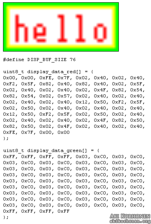
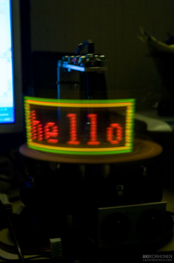
And finally, the first real test with the display fully operational and rotating. I get three colors with this setup: red, green and orange/yellowish when both red ang green are on at the same time. I drew an image with the height of 16 pixels and used pure red (255,0,0), green (0, 255, 0) and yellow (255, 255, 0). I then made a small PHP-script that will load the PNG image file that I made and it just reads every pixel from it and checks whether there is red or green on it (yellow has them both). It then outputs a piece of code that I can copy and paste on to the program code of the display. I used two 8-bit tables (one for each color) where the first byte is the data for the first 8 leds and the second byte is for the last 8 leds and so on. The table length is two times the width of the image because two bytes are used for every column.
led_display_helloworld.png
m_ak07528.jpg
Source code for the led display (version 26-07-2008):
» 20080726_led_display_2x16.c
Source code for the led display (version 29-07-2008):
» 20080729_led_display_2x16.c
(This was the code I was running on the display at Assembly "08, red and green space invader creatures, video below)
Source code for the display data converter script:
» data_generator.phps
Video clip of the display:

Another video clip of the display at Assembly "08 demoparty:
Update 2009-04-14: New videos
Drawing program:
Current features and a playable Pong game: